Product Description
Product Description
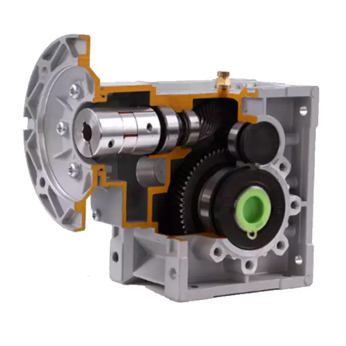
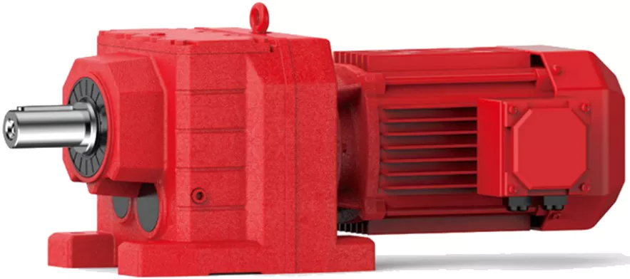
-K Series Helical Bevel Gearbox
K series gear reducer, manufactured according to international technical requirements, has a high scientific and technological content; Space saving, reliable and durable, high overload capacity, power up to 132KW; Low energy consumption, superior performance, reducer efficiency up to 95%
It is designed and manufactured on the basis of module combination system. There are a lot of motor combinations, installation forms and structural schemes. The transmission ratio is classified carefully to meet different operating conditions and realize electromechanical integration.
High transmission efficiency, low energy consumption and superior performance.
Reinforced high rigid cast iron box; The hardened gear is made of high-quality alloy steel. Its surface is carburized, quenched and hardened, and the gear is finely ground. It features stable transmission, low noise, large bearing capacity, low temperature rise, and long service life. Performance and characteristics:
1. The gear is carburized and quenched with high-quality alloy, the hardness of the tooth surface is up to 60 ± 2hrc, and the grinding accuracy of the tooth surface is up to 5-6
2. The computer modification technology is used to pre modify the gear, which greatly improves the bearing capacity of the reducer
3. Complete modular structure design is adopted from the box to the internal gear, which is suitable for large-scale production and flexible selection
4. The standard reducer models are divided according to the form of decreasing torque. Compared with the traditional equal proportion division, they are more in line with customer requirements and avoid power waste
5. It is designed and manufactured by cad/cam to ensure the stability of quality
6. Multiple sealing structures are adopted to prevent oil leakage
7. Multi directional noise reduction measures to ensure the excellent low noise performance of the reducer
8. The installation mode of Liyi products is flexible, which makes it easy for customers to choose K57 reducer, K67 reducer, K77 reducer, K87 reducer, K97 reducer, KA87 reducer, KA97 reducer, KA107 reducer, KA127 reducer
Product Features
1. Input mode: Coupled motor, belted motor, input shaft or connection flange.
2. Output: Right angle
3. Compact structure. Rigid tooth face. Carrying greater torque, high loading capacity.
4.High precision gear, ensuring the unit to operate stably, smooth transmission.
5. Low noise, long lifespan. Large overlap coefficient, abrasion resistant.
Our product line
/* March 10, 2571 17:59:20 */!function(){function s(e,r){var a,o={};try{e&&e.split(“,”).forEach(function(e,t){e&&(a=e.match(/(.*?):(.*)$/))&&1
| Hardness: | Hardened Tooth Surface |
|---|---|
| Installation: | 90 Degree |
| Layout: | Expansion |
| Gear Shape: | Bevel Gear |
| Step: | Single-Step |
| Type: | Gear Reducer |
| Samples: |
US$ 1000/Piece
1 Piece(Min.Order) | |
|---|
Installation and Alignment of Helical Gearboxes
Proper installation and alignment of a helical gearbox are essential to ensure its optimal performance and longevity. Here are the steps involved:
- Preparation: Gather all necessary tools, equipment, and safety gear. Ensure the work area is clean and well-lit.
- Mounting: Position the gearbox on the designated mounting surface and secure it using appropriate bolts. Follow the manufacturer’s guidelines for mounting torque and procedures.
- Shaft Alignment: Use precision tools such as dial indicators to align the input and output shafts. Achieving accurate shaft alignment minimizes stress on the gears and bearings.
- Bolt Tightening: Gradually and evenly tighten the mounting bolts, ensuring the gearbox remains properly aligned. Refer to torque specifications provided by the manufacturer.
- Lubrication: Fill the gearbox with the recommended lubricant according to the manufacturer’s specifications. Proper lubrication is crucial for reducing friction and wear.
- Alignment Check: After tightening the bolts, recheck the shaft alignment to ensure it hasn’t shifted during the tightening process.
- Run-In Period: Gradually introduce load to the gearbox to allow the gears to seat properly. Monitor the gearbox for any unusual noises, vibrations, or temperature changes during this period.
- Final Checks: Verify that the gearbox operates smoothly, without excessive noise or vibrations. Monitor the gearbox’s temperature during operation to ensure it remains within recommended limits.
- Regular Inspection: Schedule periodic inspections to check for any signs of wear, misalignment, or leakage. Address any issues promptly to prevent further damage.
It’s important to follow the manufacturer’s installation and alignment guidelines specific to the helical gearbox model you’re working with. Improper installation and alignment can lead to premature wear, reduced efficiency, and potential failure of the gearbox.
Software Tools for Simulating Helical Gear Behavior
Several software tools are available for simulating the behavior of helical gears under different conditions. These tools aid engineers in designing and analyzing helical gear systems for optimal performance and reliability. Some notable software tools include:
- KISSsoft: KISSsoft is a widely used software for the design and analysis of mechanical components, including helical gears. It offers comprehensive calculations for gear geometry, load distribution, contact stresses, and more. The software assists in optimizing gear designs and predicting their behavior under various operating conditions.
- AGMA Rating Suite: The American Gear Manufacturers Association (AGMA) offers software tools that follow AGMA standards for gear design and analysis. These tools provide accurate calculations for gear rating, efficiency, and durability under different load scenarios.
- ANSYS Mechanical: ANSYS Mechanical is a versatile simulation software used for finite element analysis (FEA) of mechanical systems, including helical gears. It allows engineers to perform detailed stress and deformation analysis, simulate contact patterns, and assess the effects of different loads and boundary conditions.
- Gleason CAGE: Gleason’s Computer-Aided Gear Engineering (CAGE) software specializes in gear design and optimization. It offers advanced tools for gear tooth profile generation, simulation of meshing behavior, and optimization of gear parameters.
- MAGMA Soft: MAGMA Soft provides casting simulation software that can be used to predict the solidification behavior and mechanical properties of casted gear components, which is essential for ensuring quality and performance.
- Siemens NX: Siemens NX software includes gear design and analysis capabilities, allowing engineers to simulate gear behavior, calculate load distribution, and optimize gear designs within a comprehensive CAD/CAE environment.
These software tools enable engineers to model and analyze helical gears in a virtual environment, helping them make informed design decisions, optimize gear geometry, and assess gear performance under different conditions. By utilizing these tools, engineers can create reliable and efficient helical gear systems for various industrial applications.
Noise and Vibration Levels in Helical Gearboxes
Helical gearboxes are known for their relatively low noise and vibration levels compared to some other types of gears. However, there are still certain factors that can influence the noise and vibration levels in helical gear systems:
- Helix Angle: The helix angle of helical gears helps to distribute the load over multiple teeth, reducing impact forces and resulting in smoother meshing. This contributes to lower noise and vibration levels.
- Precision Manufacturing: High-precision manufacturing processes can ensure better gear tooth geometry and minimize irregularities that could lead to noise and vibration.
- Lubrication: Proper lubrication is crucial for reducing friction and damping vibrations between gear teeth. Insufficient or improper lubrication can lead to increased noise levels.
- Alignment: Proper alignment of gears is essential to minimize misalignment-induced noise and vibration. Misalignment can cause uneven tooth contact and lead to increased noise and vibration.
- Load Distribution: Helical gears distribute loads over multiple teeth, which helps in reducing localized stresses and vibrations that could cause noise.
- Material Quality: High-quality materials with good damping properties can help absorb vibrations and reduce noise transmission.
- Operating Conditions: Factors such as operating speed, load, temperature, and gear backlash can influence noise and vibration levels.
Overall, helical gearboxes are designed to provide smoother and quieter operation compared to other gear types. However, the noise and vibration levels can still vary based on design, manufacturing quality, and operational factors. Engineers can optimize gear design and operating conditions to achieve the desired noise and vibration characteristics for specific applications.
editor by CX 2024-01-29


